Getting Started
|
The current User's Guide is very much a work in progress, any help would be greatly appreciated! |
In this section we have a look at how Openrocket is organized, by analysing in detail the structure of the user interface.
We will also briefly mention the Example projects that are accesible from the File menu.
After reading this section you will have a thorough understanding of how Openrocket is structured and will be ready to start designing a rocket of your own.
If you already know well how this program is organized, feel free to jump to the next section.
The User interface
In this subsection we first briefly discuss the Rocket Configuration window, and then Openrocket's main window and the main window's four menus.
The Rocket Configuration window
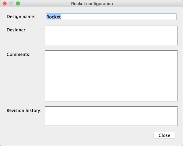
When you start a new project, you will be prompted with the following window:
Fill in the four fields (or you can leave all, except the Design name, blank if you wish) and click the close button.
Openrocket's main window
You now have access to the Openrocket main window.
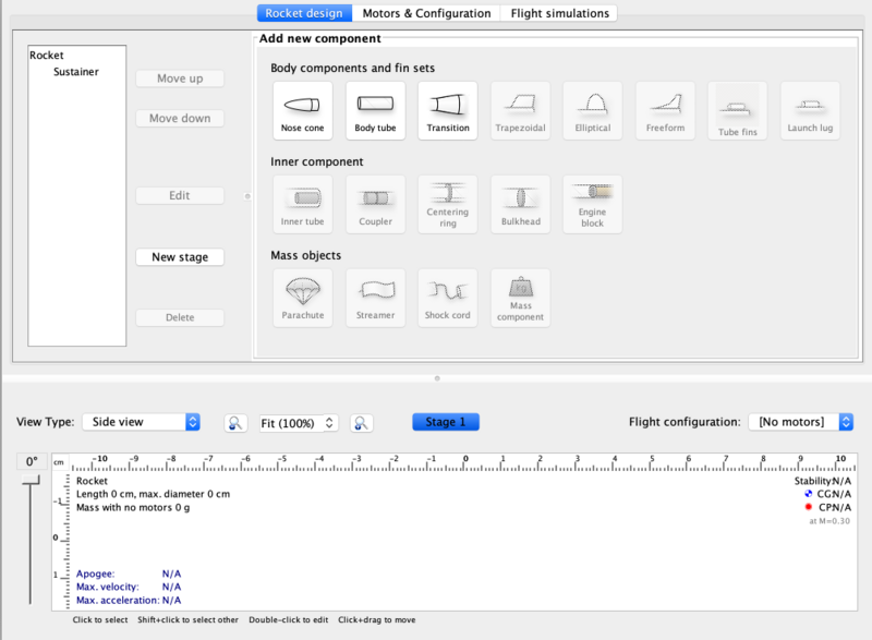
Notice there are two tabs in the top-left corner of the window, which allow you to switch between Rocket design and Flight simulations.
The Rocket design window
For the moment, let's focus on the Rocket design window. This window is organized in the following way:
- in the bottom half of the window there is a large white space. This is where a 2D image of the rocket you are designing will appear.
- in the top-left part of the window, the rocket's stages and components are shown. When you start a new project, the rocket contains only one stage, i.e. the sustainer and no components.
- in the top-right part of the window, all the body components and fin sets, inner components, and mass objects that you can add to the rocket are shown. Notice that it's not possible to add all of these object to the rocket at any particular stage of the rocket design. Exactly which components can be added when will be explained later on.
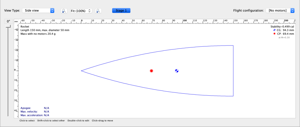
Now let's have a more close look at the bottom half of the Rocket design window. When you add a component to your rocket, it will be immediately displayed, as shown below:
Notice the rulers around the borders, which give you an idea of the dimensions of your rocket.
As you can see, not only the appearance of you rocket is shown in this part of the Rocket design window, but also some useful information, such as the rocket's dimensions, mass, apogee, max. velocity, max. acceleration, stability, center of gravity (CG), and center of pressure (CP), is shown.
In the top left-hand corner of the previous image there are two buttons, i.e. Side view and Back view, which allow you to visualise the rocket from two different positions. Next to these you can find the zoom-regulation commands and then one Stage i button for each Stage in your rocket. Selecting/deselecting each of these allows you to incluse/exlclude each stage from the picture.
On the left of the previous image you can also see a scroll bar which allows you ro rotate the rocket up to 360°.
Finally, notice the drop-down list in the top right-hand corner of the previous image. This allows you to choose which of your motor configurations to apply to the rocket you have designed (more on this later).
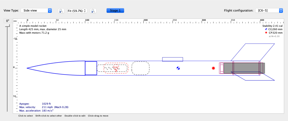
The image below shows how the bottom half of the Rocket design window appears after the rocket design has been completed.
In this image, the rocket's body components and fin sets are represented with a continous blue line, the rocket's inner components are represented with a continous red line (the inner tube is also filled in with a grey background), and the mass objects are represented with either black or red dotted lines.
It is possible to customize the colour in which each part is represented, as will be shown later on.
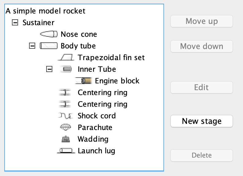
The image below shows how the top left-hand portion of the Rocket design window looks like after the rocket design has been completed.
As you can see, the rocket's components have a tree-like structure:
- the Rocket, called A simple model rocket, has only one stage, i.e. the Sustainer.
- the Sustainer contains two body components, i.e. a Nose cone and a Body tube.
- the Body tube contains a fin set (in particular a Trapezoidal fin set), a Launch lug, three inner components (an Inner Tube and two Centering rings), and three mass objects (a Shock cord, a Parachute, and a Wadding).
- the Inner tube contains an Engine block.
More on this tree-like structure will be said later on.
The buttons visible on the left in the previous image have pretty staightforward functions: by selecting one of the rocket's components you can change its position in the list of components (not its position in the rocket) by using the Move up and Move down buttons, edit its characteristics (e.g. dimensions, material, mass, colour used to represent it within the rocket) by using the Edit button, or delete it from the rocket using the Delete button. Notice that none of these buttons is active in the above image, since no component has been selected.
You can also add an extra stage to you rocket by clicking the New stage button.
The Flight simulations window
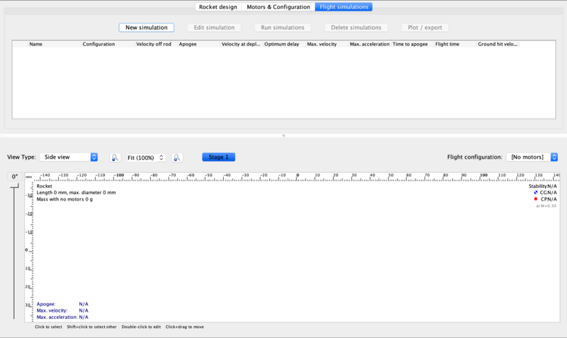
Now we have a look at the Flight simulations window, which you can access by selecting the Flight simulations tab in the top left-hand corner of the Openrocket main window. Before designing your rocket or running any flight simulation, the Flight simulations window looks like this:
Notice that the bottom part of the window does not change when switching from the Rocket Design window to the Flight simulations window.
Hence we only need to analyse the top part of the window. Here, most of the space is occupied by a currently blank space, where the technical details about your simulations will appear. Above this space there are five buttons, which allow you to program a new simulation (New simulation), edit a selected simulation (Edit simulation), for example by changing motor configuration or some atmospheric condition, run all the simulations you have programmed (Run simulations), remove the selected simulations (Remove simulations), or either plot or export some of the results of a selected simulation(Plot/export).
More on exporting simulation results in Section 8.
The image below shows how the top part of the Rocket Design window looks like after you have designed your rocket, programmed some simulations and run them.
Notice that five of the six simulations that have been run have a green tick on the left: this means that the simulation has been completed without any warnings. Conversely, if the simulation has been completed with some warning, a red exclamation mark is shown (as for the third simulation in the image above). To find out the more about the warning, position your mouse over the simulation, without clicking, as shown in the image below.
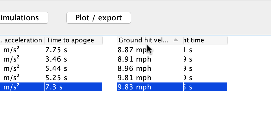
It is possible to change the position of the columns containing the various technical information about the simulations simply by dragging any column left of right, as shown below:
We now analyse the four main window's menus, briefly explaining the function of each of the menus' options.
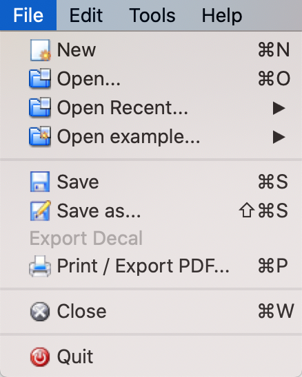
The image below shows the options offered by the File menu, located in the top left-hand corner of Openrocket's main window.
The function of each option in the File menu is pretty straightforward to understand:
- New allows you to start a new project, without closing the project that is currently open.
- Open... allows you to open a *.ork file you have saved on your computer.
- Open example... allows you to open one of the example projects (more on these later).
- Save saves the changes you have made to a previously saved projects.
- Save as... allows you to save the project you are working on to a new *.ork file.
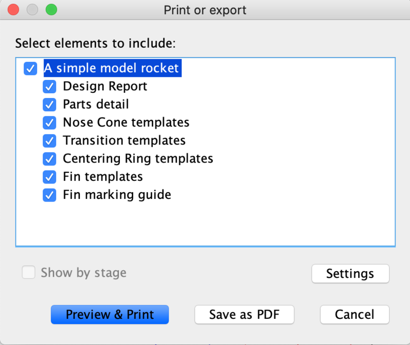
- Print/Export PDF opens a window like the one shown below (if you have already completed your rocket's design). From here you can select what to include in your print/PDF file, e.g. technical detais of your rocket's components, temmplates of your rocket's fin sets, the design of your rocket. We suggest you try this option with one of the example projects to understand how each of these is represented when printing/exporting to PDF. More on printing and exporting to PDF in Section 8.
- Close closes the project you are currently working on (after asking you whether you want to save the project if you haven't already done so) and exits the application if it was the only open project.
- Quit exits the application, checking that you have saved all open projects.
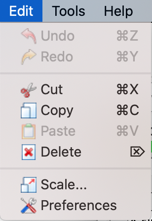
The image below shows the options offered by the Edit menu.
These options are mostly the classic editing options, i.e. undo/redo some action (Undo/Redo) and cut/copy/paste/delete some element (Cut/Copy/Paste/Delete).
We also have the following options:
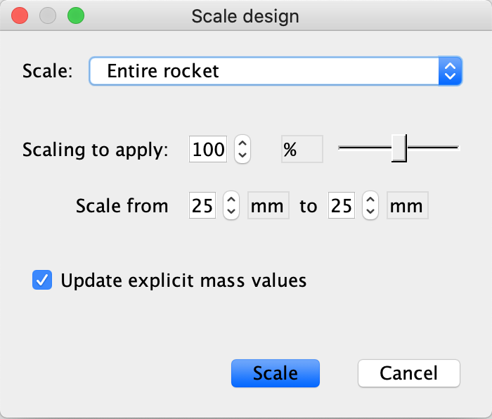
- Scale... opens the window shown below. Here you can choose to scale your rocket's size by some percentage (you can select in a range from 25% to 400%) starting from a specified dimension (which can either be the one the rocket currently has or one you specify). By checking/unchecking the Update explicit mass values you can also decide whether the rocket's mass should be updated or not when scaling the rocket's volume.
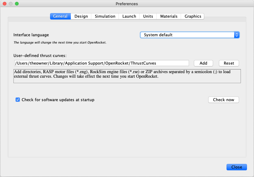
- Preferences opens the Preferences window, shown below. At the top of this window there are three tabs, which allow you to switch between Units, Materials, and Options. We consider the Units tab (shown in the picture below) of the Preferences window first. Here you can set the units for each individual physical quantity or set all units either to the Default metric or to the Default imperial.
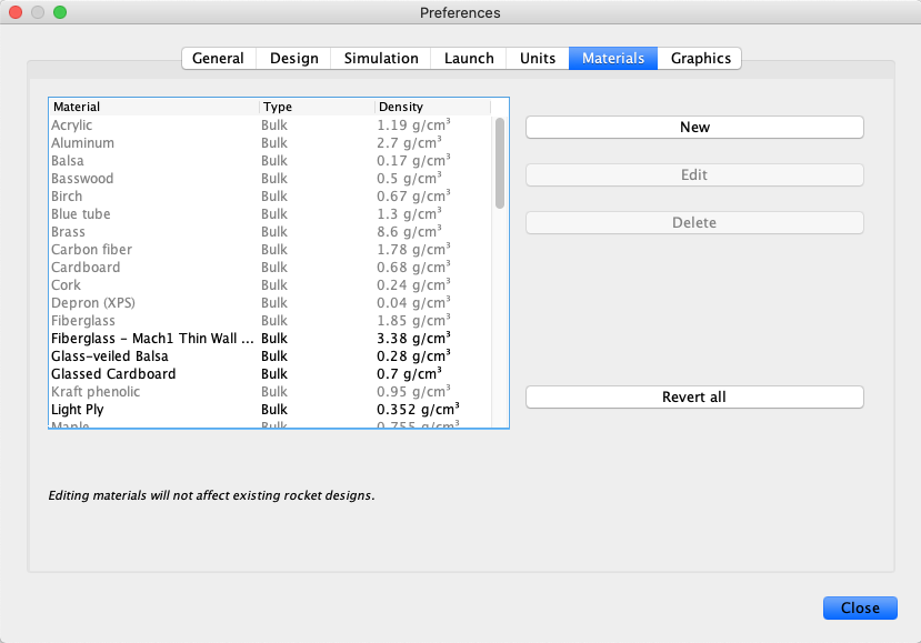
The picture below shows the Materials tab of the Preferences window. Here you can manage all the available materials for the rocket component, by either editing the characteristics of the materials (i.e. their name and density) through the Edit button or deleting some material through the Delete button. You can also add new materials if you wish, by clicking the New button and setting the material's name, type, and density.
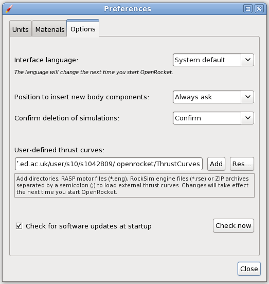
Finally, the picture below shows the Options tab of the Preferences window. Using the drop-down lists you can set the application's language, determine where to insert new rocket components, choose whether or not to ask a confirm when deleting simulations, and load some of your own thrust curves.
The image below shows the options offered by the Analyze menu.
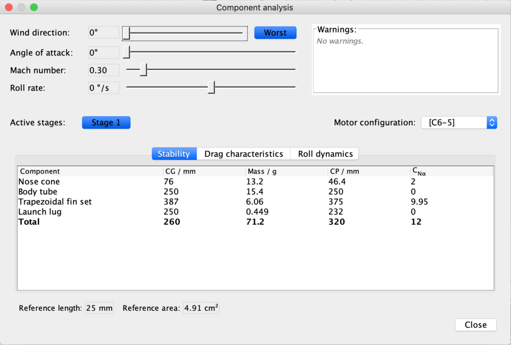
- The Component analysis option opens a window like the one shown below. Here, techical information for the rocket's external components and fin sets is shown. Using the scroll bars in the top half of the window you can also change some parameters, such as wind direction, angle of attachment, mach number, and roll rate.
More on the component analysis window in Section 8.
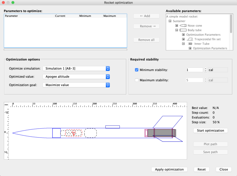
- The Rocket optimization option opens a window like the one shown below. From here you can optimize the performance of your rocket (select exactly which performance to optimize from the Optimized drop-down list).
More on the rocket optimization window in Section 8.
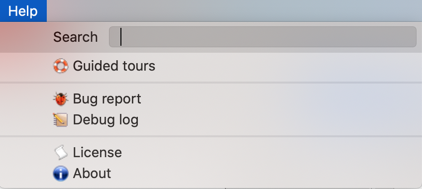
The image below shows the options offered by the Help menu.
NOTE: The guided tour option is a planned feature, but is not yet implemented into Openrocket. Hence for the moment you will not find it in the Help menu.
The functions of the options in the Help menu are as follow:
- License opens a window containing Openrocket's license.
- Bug report opens a bug report form that you can complete and send to us.
- Debug log opens the Openrocket debug log.
- About opens a window containing summary information about this project.
The Example projects
By now you should have a good idea of how Openrocket's user interface is structured.
So you might feel ready to start designing your own rocket (see next section), and probably you are indeed ready.
Nonetheless we suggest you have a look at some example pre-designed rockets that we provide. To do this, simply select File -> Open example... and the window shown in the image below will appear.
Select one or more of the listed rockets (we suggest you start with A simple model rocket.) and then click Open.
Now have a closer look at the various windows we have analysed in this section, and see how they change when you choose another example project. This should give you an idea of how to use this application at its best, and maybe even give you some new ideas for your future rockets.
Now that you know how this program is structured, you can start using Openrocket to design your own rocket. How to do this will be the topic of the next section.
