Difference between revisions of "Basic Rocket Design"
(Incremental edit--page reload) |
(Incremental edit--page reload) |
||
| Line 161: | Line 161: | ||
==== Components used in ‘A simple model rocket’ ==== | ==== Components used in ‘A simple model rocket’ ==== | ||
| − | Now we will have a quick look through the components used in the | + | Now we will have a quick look through the components used in the example rocket. If you look towards the top left of the <b>Rocket Design</b> window you will see that there is a tree of components shown. By default they should all be fully expanded. If not, do so now. |
| − | |||
| − | If you look towards the top left of the <b>Rocket Design | ||
[[File:Structure.png|thumb|1000 px|center|Top left-hand portion of the <i>Rocket design</i> window.]] | [[File:Structure.png|thumb|1000 px|center|Top left-hand portion of the <i>Rocket design</i> window.]] | ||
| − | This image shows <i>A simple model rocket</i> at the top, followed by the <b>Sustainer</b>, which is <i>Stage 1</i> of the rocket. <br/> | + | This image shows <i>A simple model rocket</i> at the top, followed by the <b>Sustainer</b>, which is <i>Stage 1</i> of the rocket. <br/><br/> |
| − | If we look at the first component in the <i> | + | If we look at the first component in the <i>Sustainer</i> stage we see that it is the nose cone. Double click on that now. This will bring up the <i>Nose cone configuration</i> window. |
[[File:ConfigNose.png|thumb|600 px|center|Nose Cone Configuration Window.]] | [[File:ConfigNose.png|thumb|600 px|center|Nose Cone Configuration Window.]] | ||
| − | As we have already examined the <i>configuration window</i> we will not repeat ourselves here. However, you will see that in this example we have used an <b>Ogive</b> nose cone with a <i> | + | As we have already examined the <i>configuration window</i> we will not repeat ourselves here. However, you will see that in this example we have used an <b>Ogive</b> nose cone with a <i>Shape parameter</i> of 1.0. If you read the description of the component to the right in the configuration window, you will discover that a value of 1.0 produces a <b>tangent ogive</b>. <br/><br/> |
| − | Moving down the window, you will see that the <b>Nose cone length</b> has a value of 10, the <b>Base diameter</b> has a value of 2.5, and the <b> Wall thickness</b> has a value of 0.2. All of these parameters have been set, in this example, to use <b>cm</b> as their unit. You should also see that this component is using <b>Polystyrene</b> as its material with a <b>Regular paint</b> finish. As you can see, the material has a | + | Moving down the window, you will see that the <b>Nose cone length</b> has a value of 10, the <b>Base diameter</b> has a value of 2.5, and the <b> Wall thickness</b> has a value of 0.2. All of these parameters have been set, in this example, to use centimeters (<b>cm</b>) as their unit. You should also see that this component is using <b>Polystyrene</b> as its material with a <b>Regular paint</b> finish. As you can see, the material has a density of 1.05 grams per centimetre cubed, and the paint is 60.0 micrometers thick. In the bottom left, the component <i>weight</i> is currently 13.2 grams. Go ahead and play around with the sliders to see how the component changes, and then change them back when you are finished. <br/> |
| − | If you move | + | If you move over to the <i>Shoulder</i> tab, you'll be able to see the size attributes of the shoulder. Again, you can play around with the sliders if you want--as long as you change them back to the original settings when you are finished. For reference these are <b>2.3, 2.0</b> and <b>0.2</b> centimeters, respectively. Also have a look through the rest of the tabs to see what has been selected. The only other thing to note is that the appearance has been customized. If you were to change to the <b>3D Finished</b> view type, you will see how the finished model looks. <br/> |
| − | + | Moving on to the <i>Body tube</i>, you can access its various attributes by double-clicking on it in the <i>Rocket design</i> window. Note how its various attributes have been set to create the current size. This is all fairly straightforward and as we have already looked into the various components earlier, we will not go into great detail here. <br/><br/> | |
| − | + | Note the eight other components that have been placed onto the <i>Body tube</i>. In descending order these are: <br/> | |
| − | |||
| − | |||
- <b>Trapezoidal fin set</b> <br/> | - <b>Trapezoidal fin set</b> <br/> | ||
- <b>Inner Tube</b> <br/> | - <b>Inner Tube</b> <br/> | ||
| − | - <b> | + | - <b>Centering Ring</b> <br/> |
| − | - <b> | + | - <b>Centering Ring</b> <br/> |
- <b>Shock Cord</b> <br/> | - <b>Shock Cord</b> <br/> | ||
- <b>Parachute</b> <br/> | - <b>Parachute</b> <br/> | ||
- <b>Wadding</b> <br/> | - <b>Wadding</b> <br/> | ||
- <b>Launch lug</b> <br/><br/> | - <b>Launch lug</b> <br/><br/> | ||
| − | |||
| − | The ninth component is place inside the <i>inner tube</i>. This is the engine block. If you look at the schematic of the rocket you will see that this is placed in front of the grey rectangle, which is the motor. To quickly address some of the other components you will | + | The <i>Inner Tube</i> in this design is used as a motor mount. You will see this if you go to the <b>Motor</b> tab in the <i>Inner Tube configuration</i> window. This means that a motor has been fitting into this piece. Upon inspection we can see that the current motor name is displayed in the <b>Flight configuration</b> drop-down list, on the right side of the main OpenRocket window. You can open this drop-down menu to select other motors that are available for use in this simulation, as well as the other example simulations that you will see on the <i>Flight simulation</i> tab. <br/> |
| + | |||
| + | The ninth component is place inside the <i>inner tube</i>. This is the engine block. If you look at the schematic of the rocket you will see that this is placed in front of the grey rectangle, which is the motor. To quickly address some of the other components, you will note that the recovery method used in this rocket is a <i>Parachute</i>: the red dashed rounded-rectangle near the nose cone of the rocket. Along with the parachute we have a <i>Shock cord</i>, which (as was discussed earlier) prevents loss of the nose cone upon deployment of the recovery system. This is shown as a long, black, dashed rounded-rectangle in the same general area as the parachute. The other black, dashed rounded-rectangle box is the <i>Wadding</i>, which is a mass component and is used here to bring the centre of gravity forward towards the nose. <br/> | ||
| − | We have now looked through the components used within | + | We have now looked through the components used within the simple model rocket example. If you would like to see other available components, see <b>Appendix A</b>. Now that we are familiar with what makes up the rocket we will go ahead and build one from scratch! <br/><br/> |
== Building ‘A simple model rocket’ == | == Building ‘A simple model rocket’ == | ||
Revision as of 19:18, 13 September 2015
|
The current User's Guide is very much a work in progress, any help would be greatly appreciated! |
Basic Rocket Design
In this section we'll look at how to design a basic rocket by examining the A simple model rocket design example. After reading this section you should have an understanding of how to start designing your own rockets. If you already know how to design your rocket, you can jump to the next section.
We will start with a brief discussion on the selection of available components, and then the components used in the A simple model rocket example. Then we'll build a rocket from scratch to see how it’s done.
Component Configuration Window
There are several types of components available to you as a rocket designer, and you can either customize these to meet your specific needs, or simply load presets from the database.
To start, let's begin a new project: File -> New. It doesn’t matter what we call it at the moment, but go ahead and save the design straight away: File -> Save your design. At this point you should be presented with a blank design window in the bottom half of the user interface.
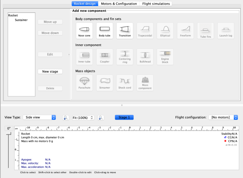
When you first start a new rocket design you will see that only three categories of components are available in the Add new component panel:
- Body components and fin sets
- Inner components
- Mass objects
We would usually start building our rocket by selecting a nose cone but for the sake of this guide click the Body tube icon in the Body components and fin sets section. This will then open up a configuration window that we'll use to edit the parameters of the body tube.
The Body Tube’ Configuration Window
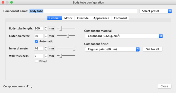
At this point you should see a new window titled Body tube configuration.
This window allows you to either select a preset for the component type you are choosing, or make your own. Let’s start by examining how to customize it ourselves. If you have a look at the Body tube configuration window you will see that at the top there is a Component name field. Here we can change the name of the current component to anything we choose. (Note that this name will then appear in the design tree seen in the Rocket Design panel of the main program window.)
Just below Component name there are several tabs:
- General: allows us to alter the basic attributes of the component.
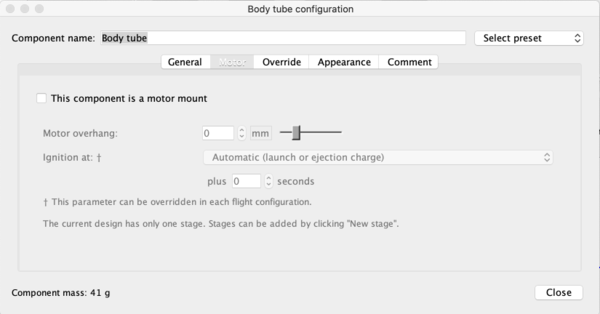
- Motor: allows us to make the body tube into a motor mount, and also edit the properties of the motor.
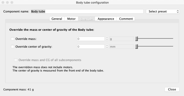
- Override: allows us to manually set the mass or centre of gravity for the component.
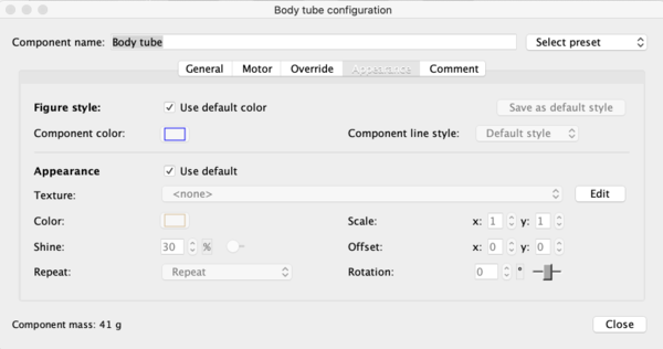
- Appearance: allows us to select colours, textures and other finishes.
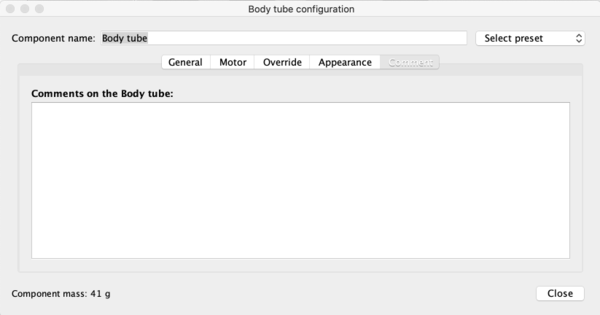
- Comment: allows us to enter any comments or notes about the component.
It should be noted that these tabs are specific to the component being designed. For example, a nose cone will not have a motor tab, but will instead have a shoulder tab. It will also have a description panel to tell you a bit more about the component you are choosing. After you learn how to navigate around one component configuration panel, the others should be relatively self-explanatory.
General Tab
The rest of the Body tube configuration window lists the different parameters for the current component type. As you can see, the General tab provides options to manually enter numbers, or you can also use the spin boxes (coarse control) or sliders (fine control) provided to adjust the parameter values. The Automatic checkbox will adjust the dimensions of the component automatically. Here you will also see a Filled checkbox. If this is checked you will notice that the inner diameter goes to zero, i.e., a filled (solid) tube. Note how the Component mass changes when this box is checked.
On the right hand side of the window you will see the Component material and Component finish drop-down menus. If you click on these you will be presented with a list of various materials and finishes, each with their own weight and thickness. If you are using the same finish for the entire rocket you can click the Set for all button to make each component use the same finish. The last notable feature in this window is in the bottom left. There you will see a live display of the Component mass. This will update automatically as you change parameter values. Experiment with the sliders to see how the component changes in the design window.
You may have noticed that, apart from the mass, there is no noticeable difference when either the inner diameter or wall thickness parameters are changed. To see those changes reflected in the model you will have to switch to a different View Type, by selecting the desired view from the drop-down list at the left of the main OpenRocket program window.
Motor Tab
Next to the General tab is the Motor tab. If you click on it you will see that most parameters are grayed-out, with the exception of one checkbox. As the label mentions, this is for when you want the body tube component to also be a motor mount.
Have a quick look at this if you wish, but we'll discuss changing flight configurations for a later section of the guide.
Override
We'll take a quick look at this tab, as it common to most components. For starting out though, you most likely will not need it.
This tab would be used when you specifically wanted to override the mass and centre of gravity (CG) of the component.
Appearance
Everyone likes something shiny, don’t they? This tab allows you edit the appearance of the component.
There are two sections here, the Figure style section and the Appearance section. Figure style changes what the 2D figure looks like, whereas Appearance will change what the 3D model will look like. If you wish to use any custom textures or images in your rocket design, you can load those through the Texture drop-down menu.
Comment
This section does not really need much explanation. If you want to write any comments or notes about your component (why you chose the values you did, etc.), then this is the place to do it.
Now that we have been through all of the tabs of the Body Tube component, click the Close button. You should now notice that the rest of the components are now unlocked in the top right of the Design window. This is because all component types can be added to a body tube. However, a Nose cone should be selected first if you are making your own rocket.
Let’s have a look at the full list of components. If you cannot click on the component type, try selecting the Body tube in the design window in the top left panel of OpenRocket.
Available Components
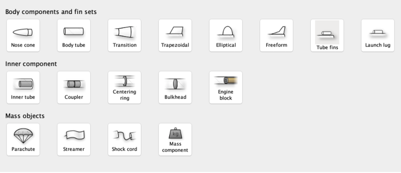
As previously mentioned, there are 16 component types to choose from within OpenRocket. These are split into three sections:
- Body components and fin sets
- Inner components
- Mass objects
Body components and fin sets
Within Body components and fin sets we have 7 component types. These components make up the external and main body of the rocket; everything else is inside the rocket. As you will see in the image the component types are:
- Nose Cone: The very tip of the rocket. Usually, you will select this component first.
- Body Tube: As we have seen, the body tube makes up the main section of a stage.
- Transition: A component that usually joins one body tube to another (normally larger) tube.
- Trapezoidal fin: A fin set that is in the shape of a trapezoid.
- Elliptical fin: A fin set that is in the shape of an ellipse.
- Freeform fin: This special kind of fin takes any shape you want. If you add it to your model it will open up a design window for you to alter the shape as desired.
- Launch Lug: This component usually goes on the outside of a body tube and is used while the rocket is on the launch pad.
Inner Components
Within Inner components we have 5 component types, and these components are all internal. As with Body components and fin sets we will now run through the list of components.
- Inner tube: This component lets you add tubes to the inside of the main body tube.
- Coupler: Used in multi-stage rockets, a coupler joins two sections together.
- Centering ring: These can be used to support other components (e.g., a motor), in the centre of a larger tube.
- Bulkhead: This is a block of material that forms a stop or barrier between two different areas.
- Engine block: An engine block prevents the motor from moving forward in the motor mount tube.
Mass Objects
Within Mass objects we have 4 component types. They are:
- Parachute: Like any good parachute, this component will stop your rocket from becoming scrap.
- Streamer: Another component for keeping your rocket safe, a streamer creates drag as your rocket falls down to earth.
- Shock cord: A shock cord secures the nose cone to the body of the rocket so that it isn't lost when the nose is blown off to deploy the parachute/streamer.
- Mass component: This is a block of mass used to adjust the rocket's Center of Gravity (CG). You can name it to whatever you want it to represent.
You have now had a brief run through the various components available for use in OpenRocket. The next section will deal with an example rocket.
A Simple Model Rocket Example
In this section we will look at the components used in the A simple model rocket example design. To get started, start OpenRocket and navigate to the main window. As a reminder it looks like this:
Opening Example Designs
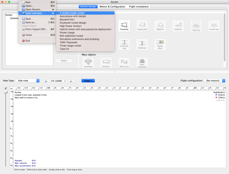
We'll begin by looking at how to find and load the example rockets within OpenRocket. Recall that this was also covered in the Getting Started section of this guide, but as a refresher the steps for doing this are as follows:
- In the main window, click on the File menu at the top left.
- Scroll down to Open Examples... open, and expand that menu. Here you will see a list of the available rocket design examples.
Your screen should now look like this:
Click on first example, our Simple model rocket. A Rocket configuration window should appear, with the Design Name (A simple model Rocket) and Designer (Sampo Niskanen) fields populated. The Comments and Revision History fields will be blank. Click Close. You should now have successfully loaded the rocket and be able to see a 2D schematic in the Rocket Design window.
Components used in ‘A simple model rocket’
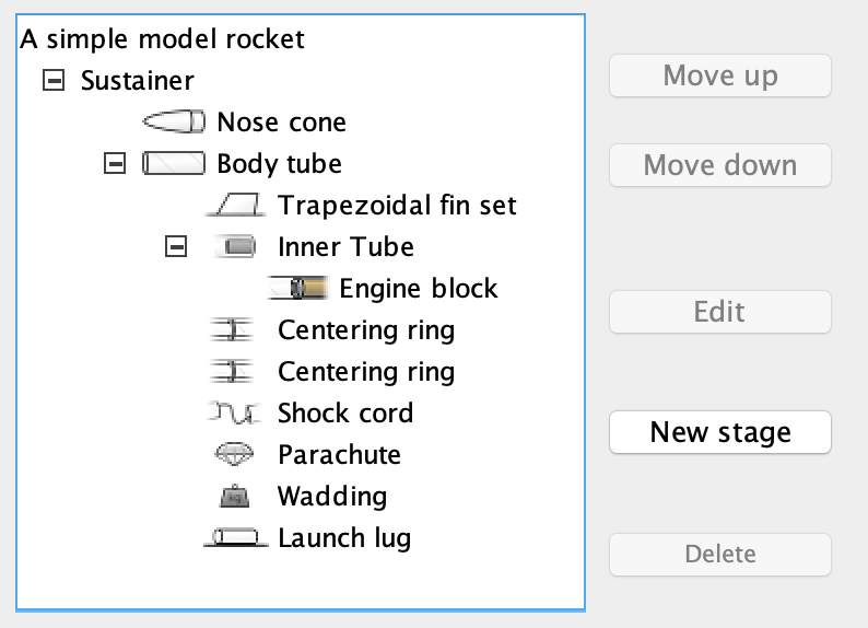
Now we will have a quick look through the components used in the example rocket. If you look towards the top left of the Rocket Design window you will see that there is a tree of components shown. By default they should all be fully expanded. If not, do so now.
This image shows A simple model rocket at the top, followed by the Sustainer, which is Stage 1 of the rocket.
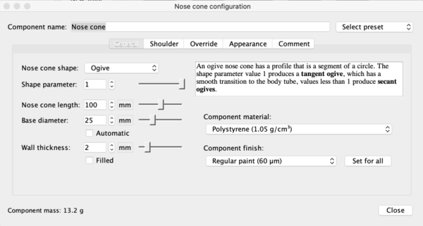
If we look at the first component in the Sustainer stage we see that it is the nose cone. Double click on that now. This will bring up the Nose cone configuration window.
As we have already examined the configuration window we will not repeat ourselves here. However, you will see that in this example we have used an Ogive nose cone with a Shape parameter of 1.0. If you read the description of the component to the right in the configuration window, you will discover that a value of 1.0 produces a tangent ogive.
Moving down the window, you will see that the Nose cone length has a value of 10, the Base diameter has a value of 2.5, and the Wall thickness has a value of 0.2. All of these parameters have been set, in this example, to use centimeters (cm) as their unit. You should also see that this component is using Polystyrene as its material with a Regular paint finish. As you can see, the material has a density of 1.05 grams per centimetre cubed, and the paint is 60.0 micrometers thick. In the bottom left, the component weight is currently 13.2 grams. Go ahead and play around with the sliders to see how the component changes, and then change them back when you are finished.
If you move over to the Shoulder tab, you'll be able to see the size attributes of the shoulder. Again, you can play around with the sliders if you want--as long as you change them back to the original settings when you are finished. For reference these are 2.3, 2.0 and 0.2 centimeters, respectively. Also have a look through the rest of the tabs to see what has been selected. The only other thing to note is that the appearance has been customized. If you were to change to the 3D Finished view type, you will see how the finished model looks.
Moving on to the Body tube, you can access its various attributes by double-clicking on it in the Rocket design window. Note how its various attributes have been set to create the current size. This is all fairly straightforward and as we have already looked into the various components earlier, we will not go into great detail here.
Note the eight other components that have been placed onto the Body tube. In descending order these are:
- Trapezoidal fin set
- Inner Tube
- Centering Ring
- Centering Ring
- Shock Cord
- Parachute
- Wadding
- Launch lug
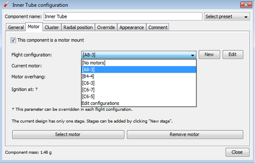
The Inner Tube in this design is used as a motor mount. You will see this if you go to the Motor tab in the Inner Tube configuration window. This means that a motor has been fitting into this piece. Upon inspection we can see that the current motor name is displayed in the Flight configuration drop-down list, on the right side of the main OpenRocket window. You can open this drop-down menu to select other motors that are available for use in this simulation, as well as the other example simulations that you will see on the Flight simulation tab.
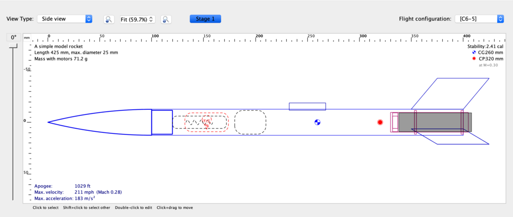
The ninth component is place inside the inner tube. This is the engine block. If you look at the schematic of the rocket you will see that this is placed in front of the grey rectangle, which is the motor. To quickly address some of the other components, you will note that the recovery method used in this rocket is a Parachute: the red dashed rounded-rectangle near the nose cone of the rocket. Along with the parachute we have a Shock cord, which (as was discussed earlier) prevents loss of the nose cone upon deployment of the recovery system. This is shown as a long, black, dashed rounded-rectangle in the same general area as the parachute. The other black, dashed rounded-rectangle box is the Wadding, which is a mass component and is used here to bring the centre of gravity forward towards the nose.
We have now looked through the components used within the simple model rocket example. If you would like to see other available components, see Appendix A. Now that we are familiar with what makes up the rocket we will go ahead and build one from scratch!
Building ‘A simple model rocket’
In this section we will build the example model up from scratch. After you have completed this you should be able to apply what you know to make any basic rocket you want. So let’s begin.
Open a new project window so that everything is blank. The following are the steps that you will need to take to create the rocket.
Select the nose cone. change its type to Ogive. Make sure that Shape parameter, Nose cone length, base diameter, and Wall thickness are set to 1.0, 10.0, 2.5, and 0.2 respectively. The units are cm by default so we do not need to change these. Do not forget to change the Component material to Polystyrene.
Next, still within nose cone, move to the shoulder tab and change the diameter to 2.3, the length to 2.0, and the thickness to 0.2. Also, check the End Capped checkbox.
The last thing we have to do with the nose cone is change the appearance so switch to that tab now. Leave the figure section alone but under Appearance change the colour to one lighter that black. (Or to whatever you want, go crazy.) Then adjust the shine to 50%. That is all we need to change for now.
You should now see this:
Next, add the Body tube. The measurements for length, outer diameter, inner diameter, and wall thickness are 30.0, 2.5, 2.3, 0.1 respectively. It may be easier to type the last two in manually rather than use the sliders. Leave automatic checked and Filled unchecked. The material will remain Cardboard and the finish will be Regular Paint. The only other thing you should change here is the appearance but I will leave that as an exercise for yourself.
You should now have this:
Moving on, we need to add a fin set. Make sure you have clicked on the body tube so that it’s highlighted then click on the Trapezoidal component type. The configuration window will have appeared. Leave the left side of the window alone: the setting there are fin as is. However, we will need to change some things on the right hand side. Firstly, change the Fin cross section to Rounded. Also, reduce the Thickness to 0.2. That’s all we need to do in this tab. Now move to the Appearance tab and customise as you will.
The next component we need to add is the Inner tube. Once again highlight the body tube and then click the inner tube component. There are a couple of attributes we should change here. Firstly, increase Length to 7.5. Also, increase plus to 0.5. Leave everything else the same. Now go to the Motor tab.
There are a few things we need to add here. To start, check the This component is a motor mount checkbox. This will allow us to add motors. The next few steps may look complicated but do not be daunted by them. First, we will deal with the easy bit. Increase the Motor overhang to 0.3. Now, where it says Flight Configuration we can see two buttons: New and Edit. Click Edit. This will bring up the Edit flight configurations window.
Make sure your window looks the same as the one above. Follow these steps:
- Click on New at the top.
- Click on Inner Tube.
- Click Select motor at the bottom. This will bring up a large list of Motors.
- Click on Designation to sort by the motor’s designation.
- Look for the A8 by Estes. Click on it.
- In the top right where it says Ejection charge delay change that to 3.
- Now click ok.
If everything went to plan, you have successfully added the Estes A8-3 motor to your rocket.
Now repeat these steps for the following motors:
- Estes B4-4
- Estes C6-3
- Estes C6-5
- Estes C6-7
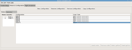
After you have added the rest of the motors, click close. If you were to expand the Flight configuration drop-down menu you should see this:
Select the A8-3 Motor for now. That is all we have to do with the Inner tube apart from the Appearance but as usual I will let you paint it how you wish.
The next component we will add is the Engine Block. This time make sure that the Inner tube is highlighted and then add an engine block component. Change the Inner diameter to 1.2 and the Wall thickness to 0.3. Also, change the Position relative to: Top of the parent component. The last change we will make is to increase plus to 0.2. That is all we have to do for this component.
Your rocket should now look like this:
We shall now add the two Centering Rings. Make sure the body tube is highlighted, then click on the Centering ring component type. The first one is fine as it is, we will not make any changes. However, we will add the following line to the comment tab: The centering ring automatically takes the outer diameter of the body tube and the inner diameter of the inner tube.
Click close, select the body tube again and add another Centering ring. This time all we have to do is to change plus to -4.5. Also, add the comment again.
The next component we will add is the Shock cord. As usual, make sure the body tube is selected before adding the shock cord component. After it has been added change plus to 2, Packed length to 5.2, and Packed diameter to 1.2. Again, we will add a comment to this component. Enter the following line to the Comment tab: The shock cord does not need to be attached to anything in particular, as it functions only as a mass component.. The shock cord has now been completed.
Now we have to add the Parachute. With the body tube highlighted, add a parachute component. Change plus to 3.2, Packed length to 4.2 and Packed diameter to 1.8. That is everything we need to do to the parachute. You can see what your rocket should now look like below.
The second last component to add is a Mass Component. Go ahead and add one to the body tube now. Adjust the Mass to 2g, the Approximate density to 0.16, the length to 3.0, the diameter to 2.3 and finally plus to 8.0. It may be easier to enter these manually. The last thing you have to do is to rename it from ‘Mass component’ to Wadding. Leave everything else as it is.
Almost done! One component left to add: the Launch Lug. Add this to the body tube now. Change the Length to 3.5, the Outer diameter to 0.7, and the inner diameter to 0.5. Leave the Thickness as it is. Also, change the Radial position to 19 degrees.
And that’s all there is to it, you have just completed building your first rocket within OpenRocket. From here you can use what you know to create more rockets or you can proceed to the next section of the User Guide: Basic Flight Simulation. Have fun!
