Difference between revisions of "Tips"
(tips page) |
Hcraigmiller (talk | contribs) |
||
| (25 intermediate revisions by 7 users not shown) | |||
| Line 1: | Line 1: | ||
| − | + | <div style="text-align: center;"> | |
| + | <div style="float: left;">[[Component Details|← Component Details (Appendix B)]]</div> | ||
| + | <div style="float: right;">[[List of useful custom expressions|List of useful custom expressions (Appendix D) →]]</div> | ||
| + | [[Main Page|↑ Back to Contents]] | ||
| + | </div> | ||
| + | {{UserGuideHelp}} | ||
| + | |||
| + | This page collects a list of short (1-3 sentences) tips for using OpenRocket. Later on they may be included in the software as a "tip of the day" system. | ||
| + | |||
| + | = General use = | ||
| + | |||
| + | * You can type in equations in the entry fields instead of numbers. For example, to double a length you can type '''3.1*2'''. | ||
| + | |||
| + | * The component tree will display any component comments as tool tips. You can set the comment on the '''Comment''' tab of the component configuration dialog. | ||
| + | |||
| + | * If you want to always load a specific .ork file, you can specify the filename as a command line argument when starting openrocket. | ||
| + | |||
| + | * You can choose your preferred units from '''Edit''' → '''Preferences...'''. You can individually change the units by clicking the unit symbol. | ||
| + | |||
| + | = Rocket design = | ||
| + | |||
| + | * A rocket design can have a number of ''motor configurations''. When simulating a flight, you select which motor configuration you use. You can edit the motor configurations using '''Tools''' → '''Motor configurations...''' | ||
* Motors can be attached to either body tubes or inner tubes. You can attach one on the '''Motor''' tab of the configuration dialog. | * Motors can be attached to either body tubes or inner tubes. You can attach one on the '''Motor''' tab of the configuration dialog. | ||
| + | |||
* You can scale a single component or an entire design using '''Edit''' → '''Scale...''' | * You can scale a single component or an entire design using '''Edit''' → '''Scale...''' | ||
| + | |||
| + | * You can define custom materials by selecting '''Custom''' from the bottom of a material selection list. | ||
| + | |||
| + | * You can select ready components from the preset dropdown on the top-right of the component editing dialog. Tick the box in the table to add the component to the dropdown menu. | ||
| + | |||
| + | * You can select components by clicking them in the diagram, or edit them by double-clicking. | ||
| + | |||
| + | * To get the best accuracy possible, you can weight your components and enter the override the calculated weight on the '''Override' tab when editing components. | ||
| + | |||
| + | * You can define through-the-wall fin tabs on the '''Fin tabs''' tab when editing a fin set. | ||
| + | |||
| + | * Your rocket's surface roughness can affect flight altitude significantly. Select the appropriate roughness on the '''Component finish''' dropdown. You can set the same finish for all components by clicking '''Set for all'''. | ||
| + | |||
| + | * You will see immediate results of a flight simulation on the lower-left corner of the design diagram. This reflects a flight with your currently selected motor configuration. | ||
| + | |||
| + | * In case OpenRocket cannot reliably compute the aerodynamic properties of the rocket, you will see warnings on the lower-right corner of the design diagram. | ||
| + | |||
| + | * You can create clustered rockets easily using the '''Cluster''' tab when editing Inner tubes. Any motors or components attached to the inner tube will be present on all copies of the inner tube. | ||
| + | |||
| + | * Centering rings, Engine blocks, Couplers and Bulkheads can automatically compute the relevant dimensions from the other components when the '''Automatic''' checkbox is selected. | ||
| + | |||
| + | * You can simulate launch rails or pins by creating filled launch lugs of the corresponding size. | ||
| + | |||
| + | * Only body components and fin sets affect the aerodynamics of the rocket. Even if an internal component extrudes outside of the body tube, its effect will not be taken into account in simulations! | ||
| + | |||
| + | * You can add stages to your rocket by pressing '''New stage''' on the main screen. Stage separation is configured on the '''Separation''' tab when editing a stage. | ||
| + | |||
| + | * You can fully customize the simulation plots on the '''Plot data''' tab. Choose one of the preset configurations or experiment with the other options. | ||
| + | |||
| + | * You can export simulated flight data to be analyzed by another program using the '''Export data''' tab when editing a simulation. | ||
| + | |||
| + | * The ball on the left side of the simulation table indicates the state of the simulation. Grey means that the simulation has not yet been run, red that the design has been changed since the simulation was last run, yellow means the data has been loaded from a file, and green means it is up-to-date. | ||
| + | |||
| + | * If a potential problem occurred during a simulated flight, you will see a red exclamation mark (!) next to your simulation. Hover over the simulation to see what the warning is about. | ||
| + | |||
| + | * You can duplicate components or move them to another design by using normal copy-paste functionality. | ||
| + | |||
| + | * You can move components by drag-dropping them in the component tree. | ||
| + | |||
| + | * You can examine details on the stability and drag characteristics of your rocket using '''Tools''' → '''Component analysis...''' | ||
| + | |||
| + | * You can optimize the shape, size or mass of your rocket using '''Tools''' → '''Rocket optimization...''' | ||
| + | |||
| + | * Custom expressions allow you to compute flight parameters that are not computed by OpenRocket by default. You define them using '''Tools''' → '''Custom expressions...''' See [https://sourceforge.net/apps/mediawiki/openrocket/index.php?title=List_of_useful_custom_expressions the wiki] for ideas. | ||
| + | |||
| + | = How To. . . = | ||
| + | |||
| + | This section is intended to demonstrate construction and simulation techniques used to implement a variety of building methods. | ||
| + | |||
| + | == Model an Adjustable Weight System == | ||
| + | |||
| + | A number of users have asked about how to implement an adjustable weight system that allows the rocket's mass to be adjusted for different configurations. The following is a basic example of how this can be done. | ||
| + | |||
| + | <font color="red">This technique requires OpenRocket 22.02 '''''beta 5 or higher'''''.</font color> | ||
| + | |||
| + | During the construction phase, component mass values are commonly updated to reflect actual measured component weights, rather than the values provided by OpenRocket. In addition, subassembly mass overrides can also be used to imitate the weight of adhesives and other elements used during construction. Ultimately, the goal is to have the total mass in OpenRocket be the same as the actual measured weight of the rocket. After accomplishing that, you may also need to add weight to adjust the rocket's center of gravity when larger motors are used. This is where adjustable weight systems come into play. | ||
| + | |||
| + | === Preparation for the Adjustable Nose Weight === | ||
| + | |||
| + | The steps to model an adjustable weight system are listed below, designated as optional or required. | ||
| + | |||
| + | 1. '''Override Component Masses''' -- If an OpenRocket provided component mass differs from the ''weighed'' component mass, then override the component mass with the actual weight. [Optional]</br> | ||
| + | 2. '''Override Subassembly Masses''' -- As subassemblies are completed, weigh the subassembly and override the primary component mass with the actual weight of the entire subassembly, checking the box to "Override mass, CG, and CD of all subcomponents". [Optional]</br> | ||
| + | 3. '''Add Construction Weight Adjustment''' -- When construction is complete, including the finish, weigh the '''''flight ready''''' rocket and measure its center of gravity from the tip of the rocket; ''flight ready means that ('''except for the motor''') the rocket could be placed on the pad and launched''. Then, add a mass component to the design (usually to the nose cone) with a mass equal to the difference between the estimated weight and the actual weight of the rocket. Once that is done, override the CG of the weight and move its distance from the tip of the rocket backward until the estimated CG matches the measured CG. <font color="red">[Required]</font color></br> | ||
| + | 4. '''Add an Adjustable Weight''' -- ''An adjustable nose weight is not an actual component''; it is a specific use of the ''Stage configuration'' overrides. Open the ''Stage configuration'' window and check the ''Override mass'' box; ''at this point it should have a value of zero''. Then, check the ''Override center of gravity'' box and set its value to the distance between the tip of the nose cone and the center of your adjustable weight system. <font color="red">'''''DO NOT'''''</font color> check the box to "Override mass, CG, and CD of all subcomponents." <font color="red">[Required]</font color></br> | ||
| + | 5. '''Additional Motors''' -- Select next motor configuration and repeat Steps 3 and 4 for each additional motor configuration.</br> | ||
| + | 6. '''Actually Add Additional Weight to Rocket''' -- ''Don't forget to '''add the additional weight to the adjustable weight system in your rocket'''.''</br> | ||
| + | |||
| + | === Using the Adjustable Nose Weight === | ||
| + | |||
| + | In OpenRocket, select the desired flight configuration (motor) and verify its stability. If a greater margin of stability is desired or required: | ||
| + | * Open the ''Stage configuration'' window and increase the override mass until the desired stability margin is reached. <font color="red">'''''DO NOT'''''</font color> change the ''Override center of gravity'' distance and <font color="red">'''''DO NOT'''''</font color> check the box to "Override mass, CG, and CD of all subcomponents."</br> | ||
| + | * '''Add''' this additional mass to your adjustable weight system.</br> | ||
| + | |||
| + | === Let's Try It. . . === | ||
| + | |||
| + | This demonstration assumes that the user understands how to implement Steps 1 through 3, above. The following requires beta 5 and above to and demonstrates how to add an adjustable nose weight system to the Apocalypse example included with OpenRocket; in this demonstration, the mass unit is in ounces and the length unit is in inches. | ||
| + | |||
| + | |||
| + | <table class="left"> | ||
| + | <tr> | ||
| + | <th></th> | ||
| + | <th>What You Do and See</th> | ||
| + | </tr> | ||
| + | <th>Step 1</th> | ||
| + | <td>Open the Apocalypse example included with OpenRocket beta 5 or higher and set the ''Flight configuration'' to "No motors." The ''Mass with no motor'' will be 141 oz. and the ''CG'' will be 41.665 in. from the tip of the rocket.</td> | ||
| + | </tr> | ||
| + | <tr> | ||
| + | <td></td> | ||
| + | <td>'''[[File:Apocolypse.01.02.Flight_Config.No_Motor.png|left|frameless|640 px|center]]'''</td> | ||
| + | </tr> | ||
| + | <th></th> | ||
| + | <td>Now, look at the ''Stage'' assembly component in the component tree, and open the ''Stage configuration'' window. Both the component tree and the stage configuration window show that the mass and CG overrides are active, including the subcomponent override.</td> | ||
| + | </tr> | ||
| + | <tr> | ||
| + | <th></th> | ||
| + | <td></td> | ||
| + | </tr> | ||
| + | <tr> | ||
| + | <td></td> | ||
| + | <td>'''[[File:Apocolypse.02.02.Stage.Config.png|left|frameless|640 px|center]]'''</td> | ||
| + | </tr> | ||
| + | <tr> | ||
| + | <th></th> | ||
| + | <td>And, because the override subcomponents box is checked, the rocket's mass is the overriden mass value and the rocket's CG is the overriden distance from the tip of the rocket to the CG.</td> | ||
| + | </tr> | ||
| + | <th></th> | ||
| + | <td></td> | ||
| + | </tr> | ||
| + | <th>Step 2</th> | ||
| + | <td>In the ''Stage configuration'' window, uncheck the override subcomponents box, then change the mass override value so that the rocket's total mass is 141 oz. (the new value should be 71.3 oz.), then change the CG override distance so that the rocket's CG is 41.665 in. from the tip of the rocket (the new value should be 38.587 in.).</td> | ||
| + | </tr> | ||
| + | <tr> | ||
| + | <th></th> | ||
| + | <td>'''[[File:Apocolypse.03.02.Stage.Config.Corrected.png|left|frameless|640 px|center]]'''</td> | ||
| + | </tr> | ||
| + | <th></th> | ||
| + | <td>In the next step, the ''Stage'' mass and CG overrides will be replaced with a mass object, freeing the ''Stage'' mass and CG overrides for use as an adjustable nose weight system.</td> | ||
| + | </tr> | ||
| + | <th>Step 3</th> | ||
| + | <td>Use a ''Mass component'' to adjust the rocket's mass and CG to the measured mass and CG (the new ''Stage'' mass and CG override values, 71.3 oz. and 38.587 in.).</td> | ||
| + | </tr> | ||
| + | <tr> | ||
| + | <th></th> | ||
| + | <td>'''[[File:Apocolypse.04.02.Nose Cone.Mass Component.png|left|frameless|640 px|center]]'''</td> | ||
| + | </tr> | ||
| + | <th></th> | ||
| + | <td>Now, open the ''Stage configuration'' window and uncheck the mass and CG overrides.</td> | ||
| + | </tr> | ||
| + | <tr> | ||
| + | <th></th> | ||
| + | <td>'''[[File:Apocolypse.05.02.Adj Nose Weight Position.png|left|frameless|640 px|center]]'''</td> | ||
| + | </tr> | ||
| + | <th></th> | ||
| + | <td>With the ''Stage'' mass and CG overrides unchecked, the rocket's total mass should be 141 oz. and the CG distance should be 41.665 in. from the tip of the rocket (the original values), and the ''Stage'' mass and CG overrides are now available to use as an adjustable weight system.</td> | ||
| + | </tr> | ||
| + | <th></th> | ||
| + | <td></td> | ||
| + | </tr> | ||
| + | <th>Step 4</th> | ||
| + | <td>Open the ''Stage configuration'' window. Check the CG override and set the value to the distance between the tip of the rocket and the center of the adjustable weight; in this demonstration, set that value to 8 in. (the vertical red line inside the nose cone is a reference point, ''for demonstration purposes only'', showing where the center of the adjustable weight system is within the rocket).</td> | ||
| + | </tr> | ||
| + | <tr> | ||
| + | <th></th> | ||
| + | <td>'''[[File:Apocolypse.07.01.Adj Nose Weight.Bulkhead.Stage.png|left|frameless|640 px|center]]'''</td> | ||
| + | </tr> | ||
| + | <th></th> | ||
| + | <td>Now, select the "J90-0" ''Motor configuration. With the motor, the CG will be 2.18 calibers.</td> | ||
| + | </tr> | ||
| + | <tr> | ||
| + | <th></th> | ||
| + | <td>'''[[File:Apocolypse.08.01.Adj Nose Weight.Bulkhead.Stage.Motor_Small.png|left|frameless|640 px|center]]'''</td> | ||
| + | </tr> | ||
| + | <th>Step 5</th> | ||
| + | <td>So, how do you maintain that stability margin with a larger motor? You use the ''Stage'' mass override, without overriding subcomponents, as an adjustable weight. Let's see how it works. Create a new motor configuration with an Aerotech L1090-0, and look at the new stability margin. It is only 1.28 calibers, well below the target of more than 2.</td> | ||
| + | </tr> | ||
| + | <tr> | ||
| + | <th></th> | ||
| + | <td>'''[[File:Apocolypse.09.01.Adj Nose Weight.Bulkhead.Stage.Motor_Large.png|left|frameless|640 px|center]]'''</td> | ||
| + | </tr> | ||
| + | <th></th> | ||
| + | <td>Open the ''Stage configuration'' window. Check the mass override box (do not check the override subcomponents box), and increase the mass until you reach the desired stability margin; in this demonstration, set that value to 20.5 oz. and the CG will again be 2.18 calibers.</td> | ||
| + | </tr> | ||
| + | <tr> | ||
| + | <th></th> | ||
| + | <td>'''[[File:Apocolypse.10.01.Adj Nose Weight.Bulkhead.Stage.Motor_Large.Corrected.png|left|frameless|640 px|center]]'''</td> | ||
| + | </tr> | ||
| + | <th>Step 6</th> | ||
| + | <td>''Don't forget to '''add the 20.5 oz. to the adjustable weight system in your rocket'''.''</td> | ||
| + | </tr> | ||
| + | </table> | ||
| + | |||
| + | For different motors, you just repeat Steps 5 and 6. It's as simple as that. | ||
| + | |||
| + | </br> | ||
| + | |||
| + | == Model Subassemblies or Subcomponents == | ||
| + | |||
| + | A number of users have asked about how to create subassemblies (subcomponents) in OpenRocket. Although OpenRocket does not currently support subassemblies directly, subassemblies can be modeled using OpenRocket's cut and paste feature, and the following example demonstrates how to this can be done. | ||
| + | |||
| + | <font color="red">This technique requires OpenRocket 22.02 '''''beta 5 or higher'''''.</font color> | ||
| + | |||
| + | === Creating and Saving a Subassembly === | ||
| + | |||
| + | One of the most common subassemblies is a motor mount, so this will be the example that is demonstrated. | ||
| + | |||
| + | <table class="left"> | ||
| + | <tr> | ||
| + | <th></th> | ||
| + | <th>What You Do and See</th> | ||
| + | </tr> | ||
| + | <th>Step 1</th> | ||
| + | <td>Open the ''A simple model rocket'' example included with OpenRocket beta 5 or higher.</td> | ||
| + | </tr> | ||
| + | <tr> | ||
| + | <td></td> | ||
| + | <td>'''[[File:Subassemblies.05.01.01.A simple model rocket.png|left|frameless|640 px|center]]'''</td> | ||
| + | </tr> | ||
| + | <th>Step 2</th> | ||
| + | <td>Use ctrl-left-click to select all of the components that will not be part of the subassembly, right-click on one of the selected components, and left-click ''Delete''.</td> | ||
| + | </tr> | ||
| + | <tr> | ||
| + | <td></td> | ||
| + | <td>'''[[File:Subassemblies.05.02.02.Highlight components to delete.png|left|frameless|640 px|center]]'''</td> | ||
| + | </tr> | ||
| + | <th>Step 3</th> | ||
| + | <td>Next, rearrange the components in the subassembly; this will be the standard order used for motor mounts. Then, for each motor mount component, open the ''Component configuration'' window and verify that the component is positioned ''Relative to the bottom of the parent component''. You also need to verify that the outer and inner diameter of each centering ring is set to ''Automatic''.</td> | ||
| + | </tr> | ||
| + | <tr> | ||
| + | <td></td> | ||
| + | <td>'''[[File:Subassemblies.05.04.05.Relative.png|left|frameless|640 px|center]]'''</td> | ||
| + | </tr> | ||
| + | <th>Step 4</th> | ||
| + | <td>Now, left-click on the body tube and open its ''Component configuration'' window. First, change the ''Component name'' to "Phantom Body tube [DO NOT COPY]." Then, change the ''Length'' and ''Wall thickness'' to "0." The motor mount is now anchored to a phantom element, so '''save this design file to your subassembly directory'''.</td> | ||
| + | </tr> | ||
| + | </table> | ||
| + | |||
| + | </br> | ||
| + | |||
| + | === How to Use a Saved Subassembly === | ||
| + | |||
| + | Although a subassembly can be copied and paseted into a near complete design, this example shows just a basic copy and paste to just a body tube. | ||
| + | |||
| + | You can start with an existing design and then open the subassembly file, or open the subassembly file before opening a new or existing design file. | ||
| + | |||
| + | <table class="left"> | ||
| + | <tr> | ||
| + | <th></th> | ||
| + | <th>What You Do and See</th> | ||
| + | </tr> | ||
| + | <th>Step 1</th> | ||
| + | <td>In this example, a new design will be started with a BT-50 Body Tube.</td> | ||
| + | </tr> | ||
| + | <tr> | ||
| + | <td></td> | ||
| + | <td>'''[[File:Subassemblies.05.06.01.New BT.png|left|frameless|640 px|center]]'''</td> | ||
| + | </tr> | ||
| + | <th>Step 2</th> | ||
| + | <td>Go to the subassembly design. Select all of the motor mount components (not the phantom body tube), then right-click on a selected component and left-click on ''Copy''.</td> | ||
| + | </tr> | ||
| + | <tr> | ||
| + | <td></td> | ||
| + | <td>'''[[File:Subassemblies.05.07.02.Copy.png|left|frameless|640 px|center]]'''</td> | ||
| + | </tr> | ||
| + | <th>Step 3</th> | ||
| + | <td>Go back to the new design. Select the body tube, then right-click on the selected body tube and left-click on ''Paste''.</td> | ||
| + | </tr> | ||
| + | <tr> | ||
| + | <td></td> | ||
| + | <td>'''[[File:Subassemblies.05.08.01.Paste.png|left|frameless|640 px|center]]'''</td> | ||
| + | </tr> | ||
| + | <th></th> | ||
| + | <td>And, this is what you get. . . a body tube with a complete motor mount. </td> | ||
| + | </tr> | ||
| + | <tr> | ||
| + | <td></td> | ||
| + | <td>'''[[File:Subassemblies.05.09.01.Pasted.png|left|frameless|640 px|center]]'''</td> | ||
| + | </tr> | ||
| + | </table> | ||
| + | |||
| + | </br> | ||
| + | |||
| + | Now that you have the basics down, the same process can be used for avionics bays and other subassembly applications. | ||
| + | |||
| + | </br> | ||
| + | |||
| + | ---- | ||
| + | <div style="text-align: center;"> | ||
| + | <div style="float: left;">[[Component Details|← Component Details (Appendix B)]]</div> | ||
| + | <div style="float: right;">[[List of useful custom expressions|List of useful custom expressions (Appendix D) →]]</div> | ||
| + | [[Main Page|↑ Back to Contents]] | ||
| + | </div> | ||
Latest revision as of 06:51, 12 October 2022
|
The current User's Guide is very much a work in progress, any help would be greatly appreciated! |
This page collects a list of short (1-3 sentences) tips for using OpenRocket. Later on they may be included in the software as a "tip of the day" system.
General use[edit]
- You can type in equations in the entry fields instead of numbers. For example, to double a length you can type 3.1*2.
- The component tree will display any component comments as tool tips. You can set the comment on the Comment tab of the component configuration dialog.
- If you want to always load a specific .ork file, you can specify the filename as a command line argument when starting openrocket.
- You can choose your preferred units from Edit → Preferences.... You can individually change the units by clicking the unit symbol.
Rocket design[edit]
- A rocket design can have a number of motor configurations. When simulating a flight, you select which motor configuration you use. You can edit the motor configurations using Tools → Motor configurations...
- Motors can be attached to either body tubes or inner tubes. You can attach one on the Motor tab of the configuration dialog.
- You can scale a single component or an entire design using Edit → Scale...
- You can define custom materials by selecting Custom from the bottom of a material selection list.
- You can select ready components from the preset dropdown on the top-right of the component editing dialog. Tick the box in the table to add the component to the dropdown menu.
- You can select components by clicking them in the diagram, or edit them by double-clicking.
- To get the best accuracy possible, you can weight your components and enter the override the calculated weight on the Override' tab when editing components.
- You can define through-the-wall fin tabs on the Fin tabs tab when editing a fin set.
- Your rocket's surface roughness can affect flight altitude significantly. Select the appropriate roughness on the Component finish dropdown. You can set the same finish for all components by clicking Set for all.
- You will see immediate results of a flight simulation on the lower-left corner of the design diagram. This reflects a flight with your currently selected motor configuration.
- In case OpenRocket cannot reliably compute the aerodynamic properties of the rocket, you will see warnings on the lower-right corner of the design diagram.
- You can create clustered rockets easily using the Cluster tab when editing Inner tubes. Any motors or components attached to the inner tube will be present on all copies of the inner tube.
- Centering rings, Engine blocks, Couplers and Bulkheads can automatically compute the relevant dimensions from the other components when the Automatic checkbox is selected.
- You can simulate launch rails or pins by creating filled launch lugs of the corresponding size.
- Only body components and fin sets affect the aerodynamics of the rocket. Even if an internal component extrudes outside of the body tube, its effect will not be taken into account in simulations!
- You can add stages to your rocket by pressing New stage on the main screen. Stage separation is configured on the Separation tab when editing a stage.
- You can fully customize the simulation plots on the Plot data tab. Choose one of the preset configurations or experiment with the other options.
- You can export simulated flight data to be analyzed by another program using the Export data tab when editing a simulation.
- The ball on the left side of the simulation table indicates the state of the simulation. Grey means that the simulation has not yet been run, red that the design has been changed since the simulation was last run, yellow means the data has been loaded from a file, and green means it is up-to-date.
- If a potential problem occurred during a simulated flight, you will see a red exclamation mark (!) next to your simulation. Hover over the simulation to see what the warning is about.
- You can duplicate components or move them to another design by using normal copy-paste functionality.
- You can move components by drag-dropping them in the component tree.
- You can examine details on the stability and drag characteristics of your rocket using Tools → Component analysis...
- You can optimize the shape, size or mass of your rocket using Tools → Rocket optimization...
- Custom expressions allow you to compute flight parameters that are not computed by OpenRocket by default. You define them using Tools → Custom expressions... See the wiki for ideas.
How To. . .[edit]
This section is intended to demonstrate construction and simulation techniques used to implement a variety of building methods.
Model an Adjustable Weight System[edit]
A number of users have asked about how to implement an adjustable weight system that allows the rocket's mass to be adjusted for different configurations. The following is a basic example of how this can be done.
This technique requires OpenRocket 22.02 beta 5 or higher.
During the construction phase, component mass values are commonly updated to reflect actual measured component weights, rather than the values provided by OpenRocket. In addition, subassembly mass overrides can also be used to imitate the weight of adhesives and other elements used during construction. Ultimately, the goal is to have the total mass in OpenRocket be the same as the actual measured weight of the rocket. After accomplishing that, you may also need to add weight to adjust the rocket's center of gravity when larger motors are used. This is where adjustable weight systems come into play.
Preparation for the Adjustable Nose Weight[edit]
The steps to model an adjustable weight system are listed below, designated as optional or required.
1. Override Component Masses -- If an OpenRocket provided component mass differs from the weighed component mass, then override the component mass with the actual weight. [Optional]
2. Override Subassembly Masses -- As subassemblies are completed, weigh the subassembly and override the primary component mass with the actual weight of the entire subassembly, checking the box to "Override mass, CG, and CD of all subcomponents". [Optional]
3. Add Construction Weight Adjustment -- When construction is complete, including the finish, weigh the flight ready rocket and measure its center of gravity from the tip of the rocket; flight ready means that (except for the motor) the rocket could be placed on the pad and launched. Then, add a mass component to the design (usually to the nose cone) with a mass equal to the difference between the estimated weight and the actual weight of the rocket. Once that is done, override the CG of the weight and move its distance from the tip of the rocket backward until the estimated CG matches the measured CG. [Required]
4. Add an Adjustable Weight -- An adjustable nose weight is not an actual component; it is a specific use of the Stage configuration overrides. Open the Stage configuration window and check the Override mass box; at this point it should have a value of zero. Then, check the Override center of gravity box and set its value to the distance between the tip of the nose cone and the center of your adjustable weight system. DO NOT check the box to "Override mass, CG, and CD of all subcomponents." [Required]
5. Additional Motors -- Select next motor configuration and repeat Steps 3 and 4 for each additional motor configuration.
6. Actually Add Additional Weight to Rocket -- Don't forget to add the additional weight to the adjustable weight system in your rocket.
Using the Adjustable Nose Weight[edit]
In OpenRocket, select the desired flight configuration (motor) and verify its stability. If a greater margin of stability is desired or required:
- Open the Stage configuration window and increase the override mass until the desired stability margin is reached. DO NOT change the Override center of gravity distance and DO NOT check the box to "Override mass, CG, and CD of all subcomponents."
- Add this additional mass to your adjustable weight system.
Let's Try It. . .[edit]
This demonstration assumes that the user understands how to implement Steps 1 through 3, above. The following requires beta 5 and above to and demonstrates how to add an adjustable nose weight system to the Apocalypse example included with OpenRocket; in this demonstration, the mass unit is in ounces and the length unit is in inches.
| What You Do and See | |
|---|---|
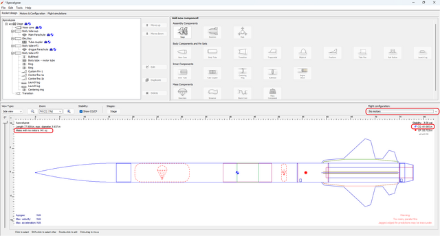
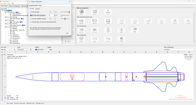
| Step 1 | Open the Apocalypse example included with OpenRocket beta 5 or higher and set the Flight configuration to "No motors." The Mass with no motor will be 141 oz. and the CG will be 41.665 in. from the tip of the rocket. |
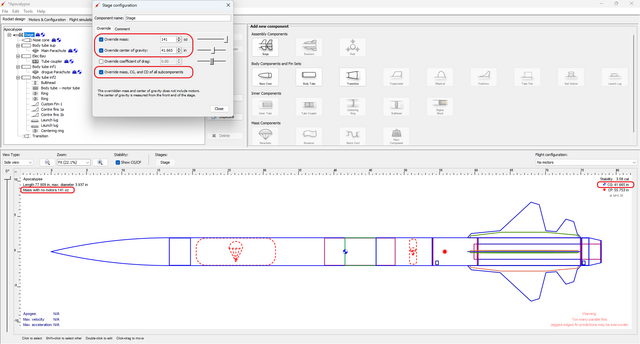
| Now, look at the Stage assembly component in the component tree, and open the Stage configuration window. Both the component tree and the stage configuration window show that the mass and CG overrides are active, including the subcomponent override. | |
| And, because the override subcomponents box is checked, the rocket's mass is the overriden mass value and the rocket's CG is the overriden distance from the tip of the rocket to the CG. | |
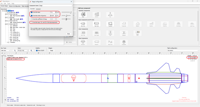
| Step 2 | In the Stage configuration window, uncheck the override subcomponents box, then change the mass override value so that the rocket's total mass is 141 oz. (the new value should be 71.3 oz.), then change the CG override distance so that the rocket's CG is 41.665 in. from the tip of the rocket (the new value should be 38.587 in.). |
| In the next step, the Stage mass and CG overrides will be replaced with a mass object, freeing the Stage mass and CG overrides for use as an adjustable nose weight system. | |
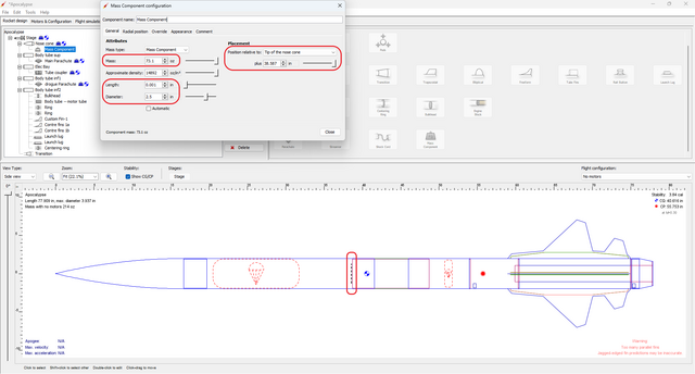
| Step 3 | Use a Mass component to adjust the rocket's mass and CG to the measured mass and CG (the new Stage mass and CG override values, 71.3 oz. and 38.587 in.). |
| Now, open the Stage configuration window and uncheck the mass and CG overrides. | |
| With the Stage mass and CG overrides unchecked, the rocket's total mass should be 141 oz. and the CG distance should be 41.665 in. from the tip of the rocket (the original values), and the Stage mass and CG overrides are now available to use as an adjustable weight system. | |
| Step 4 | Open the Stage configuration window. Check the CG override and set the value to the distance between the tip of the rocket and the center of the adjustable weight; in this demonstration, set that value to 8 in. (the vertical red line inside the nose cone is a reference point, for demonstration purposes only, showing where the center of the adjustable weight system is within the rocket). |
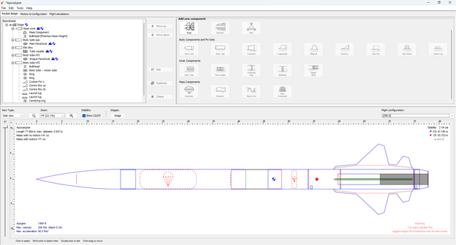
| Now, select the "J90-0" Motor configuration. With the motor, the CG will be 2.18 calibers. | |
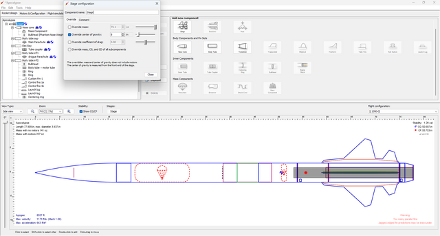
| Step 5 | So, how do you maintain that stability margin with a larger motor? You use the Stage mass override, without overriding subcomponents, as an adjustable weight. Let's see how it works. Create a new motor configuration with an Aerotech L1090-0, and look at the new stability margin. It is only 1.28 calibers, well below the target of more than 2. |
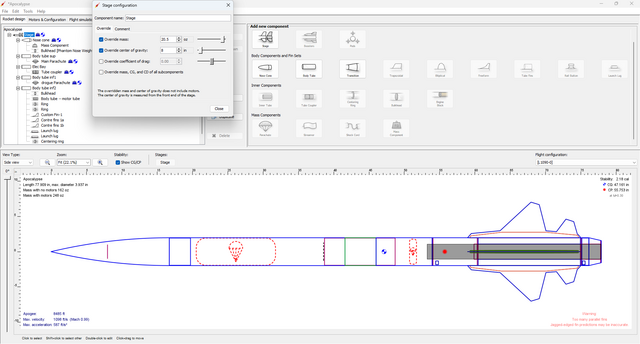
| Open the Stage configuration window. Check the mass override box (do not check the override subcomponents box), and increase the mass until you reach the desired stability margin; in this demonstration, set that value to 20.5 oz. and the CG will again be 2.18 calibers. | |
| Step 6 | Don't forget to add the 20.5 oz. to the adjustable weight system in your rocket. |
For different motors, you just repeat Steps 5 and 6. It's as simple as that.
Model Subassemblies or Subcomponents[edit]
A number of users have asked about how to create subassemblies (subcomponents) in OpenRocket. Although OpenRocket does not currently support subassemblies directly, subassemblies can be modeled using OpenRocket's cut and paste feature, and the following example demonstrates how to this can be done.
This technique requires OpenRocket 22.02 beta 5 or higher.
Creating and Saving a Subassembly[edit]
One of the most common subassemblies is a motor mount, so this will be the example that is demonstrated.
| What You Do and See | |
|---|---|
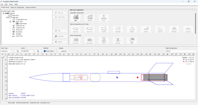
| Step 1 | Open the A simple model rocket example included with OpenRocket beta 5 or higher. |
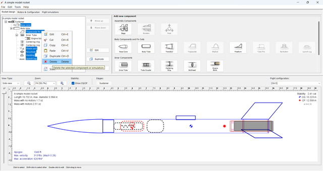
| Step 2 | Use ctrl-left-click to select all of the components that will not be part of the subassembly, right-click on one of the selected components, and left-click Delete. |
| Step 3 | Next, rearrange the components in the subassembly; this will be the standard order used for motor mounts. Then, for each motor mount component, open the Component configuration window and verify that the component is positioned Relative to the bottom of the parent component. You also need to verify that the outer and inner diameter of each centering ring is set to Automatic. |
| Step 4 | Now, left-click on the body tube and open its Component configuration window. First, change the Component name to "Phantom Body tube [DO NOT COPY]." Then, change the Length and Wall thickness to "0." The motor mount is now anchored to a phantom element, so save this design file to your subassembly directory. |
How to Use a Saved Subassembly[edit]
Although a subassembly can be copied and paseted into a near complete design, this example shows just a basic copy and paste to just a body tube.
You can start with an existing design and then open the subassembly file, or open the subassembly file before opening a new or existing design file.
| What You Do and See | |
|---|---|
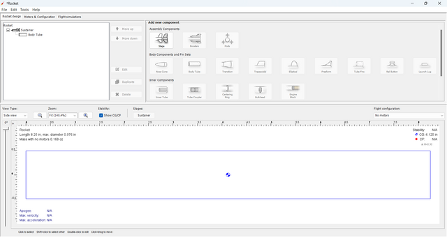
| Step 1 | In this example, a new design will be started with a BT-50 Body Tube. |
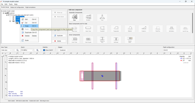
| Step 2 | Go to the subassembly design. Select all of the motor mount components (not the phantom body tube), then right-click on a selected component and left-click on Copy. |
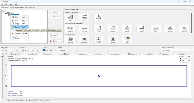
| Step 3 | Go back to the new design. Select the body tube, then right-click on the selected body tube and left-click on Paste. |
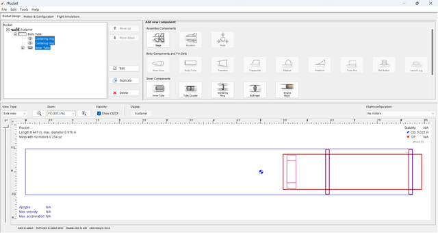
| And, this is what you get. . . a body tube with a complete motor mount. | |
Now that you have the basics down, the same process can be used for avionics bays and other subassembly applications.
